Ground (P0-P5)
![[Translate to English:] Kontakt](/fileadmin/media/steinmeyer/kontakt.jpg)
Contact
Under +49(0)7431 1288-0 we are at your disposal.
Your desired size is not listed? We also manufacture individually. Give us a call!
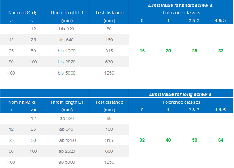
These geometric tolerances apply whenever there are no further information. The charts below apply for all ground ball screws.
For Measuring of run-out tolerances on shaft, we recommend to hold the shaft between centers and turn it consistently during the measurement. To measure the concentricity of the nut, it is necessary to turn the nut on the shaft while the shaft stands still.
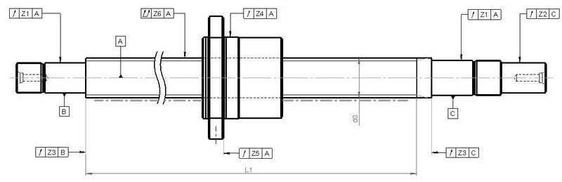
Concentricity
Radial run-out Z1 (modify Measuring E 6.2 according to DIN ISO 3408)
Nominal-Ø [mm] | P0 [µm] | P1 [µm] | P3 [µm] | P5 [µm] |
|---|---|---|---|---|
3 - 8 | 3 | 5 | 8 | 10 |
10 - 12 | 4 | 5 | 8 | 11 |
16 - 20 | 4 | 6 | 9 | 12 |
25 - 32 | 5 | 7 | 10 | 13 |
36 - 50 | 6 | 8 | 12 | 15 |
60 - 80 | 7 | 9 | 13 | 17 |
100 - 160 | - | 10 | 15 | 20 |
Radial run-out Z2 (modify Measuring E 7.2 according to DIN ISO 3408)
Nominal-Ø [mm] | P0 [µm] | P1 [µm] | P3 [µm] | P5 [µm] |
|---|---|---|---|---|
3 - 8 | 3 | 5 | 8 | 10 |
10 - 12 | 4 | 5 | 8 | 11 |
16 - 20 | 4 | 6 | 9 | 12 |
25 - 32 | 5 | 7 | 10 | 13 |
36 - 50 | 6 | 8 | 12 | 15 |
60 - 80 | 7 | 9 | 13 | 17 |
100 - 160 | - | 10 | 15 | 20 |
Radial run-out Z4 (modify Measuring E 10 according to DIN ISO 3408)
Run-out Z6 (modify Measuring E 5 according to DIN ISO 3408)